
Project at Purdue University
The Project Intro:
The purpose of the project is to build an autonomous robot that searches for metallic mines and flags them for removal by trained experts. For easy transport of this robot, it should be able to fit in a 12 cubic inch box. This report describes the methods used in the construction of the robot and the design used for the controller’s code. Using several infrared proximity sensors, motor encoders and PID controls we were able to make the robot autonomous. For this project the code has been written in the Arduino environment and the Arduino Uno microcontroller has been used.
Competition Requirements:
- The robot should be autonomous.
- The robot should fit in a 12 in3 box.
- Robot should mark and detect all the dummy mines located on the stage in under 90 seconds.
- Robot must mark dummy mines in a manner that doesnt affect the color and moisture content of the stage.
- Robot should be less than 5 kg if it has to run over the mine.
The competition stage will be a 7 ft x 7 ft flat surface.
THE Robot:
The Robot:
1. Construction:
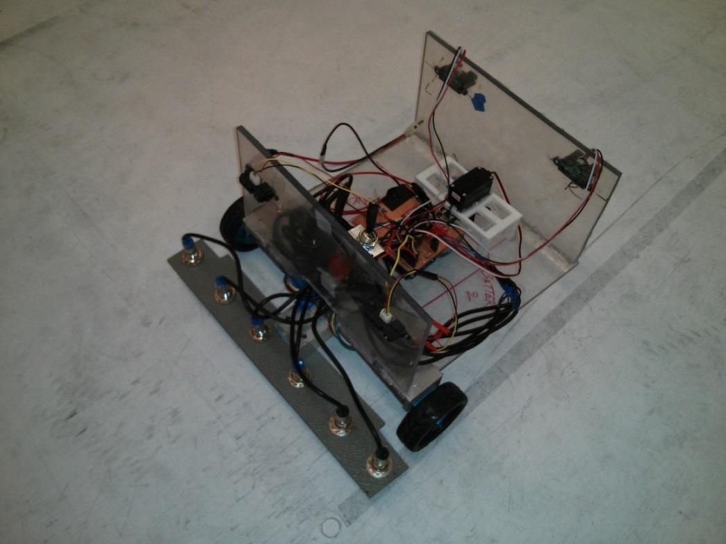
The construction and design of the robot has been kept very simple in order to lower costs and complexity. The body of the robot is made of plexi-glass and the metal sensor bar has been made from plastic. The dimensions of the robot are 12in x 12in x 9in. This complies with the specified objective that the robot should fit into a box measuring 12in x 12in x 12in.
2. Components:
The list of the major components used in the robot comprise of the following:
- 6 Inductive Proximity Sensors: The Inductive Proximity Sensors are used to detect the metallic mines. These sensors have a vertical detection range of 4mm and thus have been placed at an appropriate distance from the ground level. Using six such sensors, arranged horizontally, gives us a wider range and a higher chances of detecting the mine. Also it reduces the time taken in order to detect the mines on the arena by reducing the number of passes that the robot has to make.
- Infrared Sensors: Four infrared sensors have been used on this robot, two in the front and 2 at the rear of the robot. The front sensors help detect the wall of the arena and help initiate turning if the bot. The rear sensors help align the bot in a straight line after the 180 degree turn has been completed.
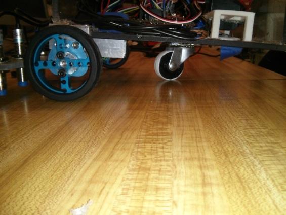
- Motors with Encoders: The robot has a front wheel drive system. There are two motor driven wheels at the front with encoders pre built into the motors. A single swivelling caster wheel is placed at the center of the robot. The encoders help in making the turning sequences better and the swivelling caster wheel doesn’t drag along the floor. This helps prevent wheel slippage, thereby giving a smooth motion. The motors used are 47:1 geared motors with encoders having 48 CPR. (Counts per Revolution).
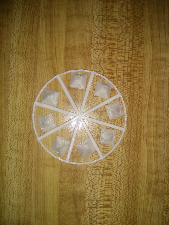
- Servo motor: A single continuous rotation servo motor has been used for dropping markers in order to mark the mines. The servo is set on a 3D printed table arrangement and a 8 spoke wheel is attached to the servo horn. 7 markers are placed in the spaces between the wheel spokes. When a mine is detected, the servo rotates a set number of degrees and drops the marker through a hole in the base of of the robot.
- Switch: A simple toggle switch is used to turn the robot on and off.
- Printed Circuit Board: A PCB has been fabricated in order to reduce the mess of jumper cables and wires on the robot. This provides for a cleaner setup and the PCB acts as a shield for the Arduino Uno.
- Arduino Uno: The Arduino Uno microcontroller has been used as the ‘brain’ of the robot. The coding is done on the Arduino platform.
- Battery: A 7.2V, 3000 mAH NiMH battery is used as the powerhouse of the robot.
3. Operation:
The operation of the robot is divided into three functions – Moving straight, turning and detect & mark.
- Function 1 – Moving straight: Several techniques were tried to make the robot run in a straight line. Initially, the robot had front wheel drive with two non-swivel wheels at the back. With this design the robot kept deviating from a straight line. To correct this problem, the rear wheels were replaced by two swivel caster wheels. But this did not correct the problem as one of the wheels had constructional issues. Removing this wheel and having just one swivel caster wheel at back allowed the robot move a better than before in a straight line but it still had issues. Finally, we added a PID controller in the code.
- Function 2 – Turning Sequence: The turning sequence was a bit tricky to achieve. We wanted the robot to sweep the whole field in the minimum amount of time and we decide to a zig-zag pattern for this. The front IR Sensors helped detect the wall of the arena. After the wall is detected, the turning sequence is initiated. First, it was decided that the encoders complete the turn till about 160 degrees and then the back IR Sensors take over in order to complete the rest of the 180 degree turn till the bot aligns in a straight line with the wall and begins moving forward again. However the non-linearity of the IR Sensors made this process difficult.
Thus, in the final iteration, the back IR Sensors were scrapped and only the encoders were used to complete the turning sequence.
- Function 3 – Detect & Mark: To detect the dummy mines, 6 inductive proximity sensors are used. These sensors are laid horizontally on a bar in front of the robot. The gap between these sensors and the ground is measured so that the sensors are less than 4mm away from the mines. These sensors output a high signal when they detect a mine. All 6 sensors are integrated as one in the Arduino code. So if any one of the sensors output a high signal, the code calls in the marking sequence. Since there are 4 mines, we decided to use a continuous servo rather than a standard servo. The horns on the continuous servo are attached to a 3D printed 8 spoke wheel. Between every spoke we placed a marker, thus giving us 8 markers and allowing us to have spare markers in case we double mark a mine. These markers are in a pyramid shape; this shape is used to prevent the marker from rolling. For every detection, the servo rotates for 0.25 seconds and the marker falls through the hole made on the body of the robot.
4. Circuitry:
The circuitry and its relating subsystems could be discribed as below:
Powering system:
A 7.2 V, 3000 mAH (NiMH) VEX battery is used in the circuit, and both the locigal parts and the Acutator parts are powered using by the battery. The 5V powersupply of the arduino board is not used during the final design of the system. A 7805 voltage ragulator is used to do the voltage devision, enables the atuators– including the marking servo motor and the wheel motor, the detectors –including the IR sensors and the metal sensors, and the logical circuitry providor – which is the Arduino Uno board.
The signal processing and locigal system:
The front IR sensors are used to determing if a turning function is needed, once it is triggered, the turning function will be called. With turning function called, the robot began to turn with either wheel stopped while another wheel is doing forwarding function. The back IR sensors are used to determing if a turning process could be terminated. The mine detecting function is also running as a parallel mission, once a mine is detected, the marking servo motor would be activated and a marker is placed.
To decrease the effect of noise for the IR sensors and metal sensors, capacitors are used to filter out the high frequency noises that may affect the working conditions for the sensors. These noise can distract the algorithm and then affect the working robot. Also the 6 metal sensors are regarded as one signal input in the circuitry design as they serve the same function in the state machine of the robot.
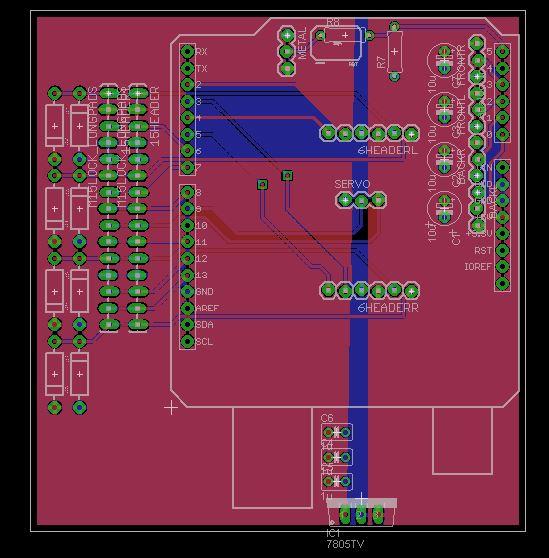
The PCB board:
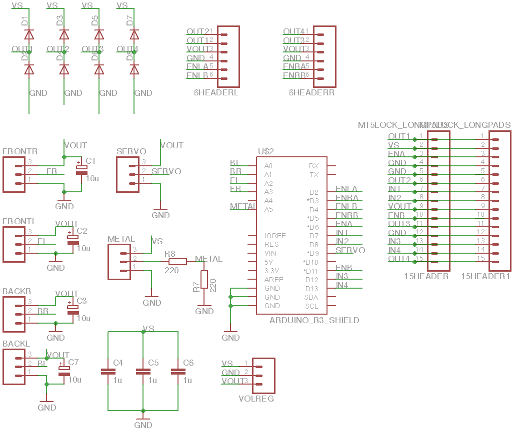
The PCB designing software, EagleCAD is used to do the design and wiring process of the shield. Manually wiring is used as auto wiring may fail and leads to unexpected situations once the circuit is applied. In the circuit diagram, two 15 pin header is used. This is because the H bridge has a male header and it would be difficult to get it connected with the circuit. To solve this problem, we used a female header and a male header in the PCB. The male header works as a sets of vias while the female header is directedly connected with the h bridge.
The PCB serves as a shield for the Arduino Uno board. This reduces the number of wires and jumper cables used and gives a cleaner setup.


5. Algorithm and woring process:
The 7.2 V battery is connected to the PCB through a switch. On turning the switch on, the battery directly powers the motors and the inductive proximity sensors. The 2 motors are operated using a LM298 H-bridge motor driver. A 7805 Voltage regulator steps down the voltage to 5 V for powering the Arduino Uno board, the IR Sensors and the servo motor. The PID control helps make the robot move in a straight line. When a wall is detected by the front IR Sensors, the encoders help make the robot turn 180 degrees about a pivoted wheel. After the turn is completed, the bot moves in a straight line again. This process continuous till the complete arena is swept. If a mine is detected by the metal sensors during movement, the servo motor is activated. The servo then turns a specified angle in order to drop the marker near the mine. After the marking, the robot resumes its motion again.
Circuit Diagram
The circuit has been made using EagleCAD.
Arduino Code

#define in3Pin 12                  //Defining the Arduino Pins
#define in4Pin 13
#define LAencoderPin 2
#define RAencoderPin 3
#define LBencoderPin 4
#define RBencoderPin 5
#define servoPin 9
#define in1Pin 7
#define in2Pin 8
#define LpwmPin 6
#define RpwmPin 11
#define metalPin A5
#define frontRightIRPin A3
#define backLeftIRPin A0
#define backRightIRPin A1
#define frontLeftIRPin A2
#include <Servo.h>

Servo flag;                      //Marking Servo Values
int time = 850 / 4;
int pos = 115;
int prox1read;

int markCount = 0;
int val1;                      // right IRs
int val2;                      // left IRs
long sum1;                   //back right IR sum
long sum2;                   //back left IR sum
long j;                      //count for summation front IR
volatile long encoder0PosL = 0; //encoder count for left motor
volatile long encoder0PosR = 0; //encoder count for right motor

int count = 0;                 //Switches turn direction
int loopend;
int LpConstant;
int RpConstant;
int millisHolder;
int lastMark = 0;          //records time of last marking
int turn = 5000;           //encoder ticks for turn  old 3600

int go = 255;             //PWM for Straight, Low Voltage: 255, High Voltage: 245
int turnSpeed = 120;      //PWM for Turns, Low Voltage: 120(recent) 130, High Voltage: 100
int startTurn = 120;      //Low Voltage: 140    High Voltage:

void setup() {
  Serial.begin (9600);
  flag.attach(9);
  pinMode(metalPin, INPUT);
  flag.write(95);

  pinMode(in1Pin, OUTPUT);
  pinMode(in2Pin, OUTPUT);
  pinMode(in3Pin, OUTPUT);
  pinMode(in4Pin, OUTPUT);
  pinMode(LpwmPin, OUTPUT);
  pinMode(RpwmPin, OUTPUT);

  pinMode(LAencoderPin, INPUT);
  pinMode(LBencoderPin, INPUT);
  pinMode(RAencoderPin, INPUT);
  pinMode(RBencoderPin, INPUT);

  attachInterrupt(0, doEncoderL, CHANGE);  // encoder pin on interrupt 0 - pin 2
  attachInterrupt(1, doEncoderR, CHANGE);  // encoder pin on interrupt 1 - pin 3
  digitalWrite(in1Pin, HIGH);
  digitalWrite(in2Pin, LOW);
  digitalWrite(in3Pin, HIGH);
  digitalWrite(in4Pin, LOW);

}

void loop() {

  if (count == 4) count = 1;

  digitalWrite(in2Pin, LOW);
  digitalWrite(in4Pin, LOW);
  digitalWrite(in1Pin, HIGH);
  digitalWrite(in3Pin, HIGH);

  encoder0PosL = 0;
  encoder0PosR = 0;

  do {
    if (markCount >= 7) {                                        //Marking count
      analogWrite(LpwmPin, 0);
      analogWrite(RpwmPin, 0);
      while (1) {
        delay(0);
      }
    }

    sum1 = 0;
    sum2 = 0;
    LpConstant = -(encoder0PosL - encoder0PosR) + go;            //PID for straight movement
    if (LpConstant > 255) LpConstant = 255;
    if (LpConstant < 0) LpConstant = 0;
    RpConstant = (encoder0PosL - encoder0PosR) + go;
    if (RpConstant > 255) RpConstant = 255;
    if (RpConstant < 0) RpConstant = 0;
    analogWrite(LpwmPin, LpConstant);
    analogWrite(RpwmPin, RpConstant);
    if ((digitalRead(metalPin) == LOW) && (millis() - lastMark >= 300)) {
      markingfunc();
      lastMark = millis();
      digitalWrite(in1Pin, HIGH);
      digitalWrite(in3Pin, HIGH);
      markCount++;
    }

    for (j = 1; j <= 100; j++) {
      val1 = analogRead(frontLeftIRPin);
      val2 = analogRead(frontRightIRPin);
      sum1 = sum1 + val1;
      sum2 = sum2 + val2;
    }
    sum2 = sum2 + 2000;
  }
  while (sum1 / 100 < startTurn && sum2 / 100 < startTurn);


  if (count % 2 == 0) {               //Turn Sequence
    analogWrite(LpwmPin, 0);
    encoder0PosR = 0;
    while (encoder0PosR < turn) {
      if ((digitalRead(metalPin) == LOW) && (millis() - lastMark >= 300)) {
        digitalWrite(in1Pin, LOW);
        digitalWrite(in3Pin, LOW);
        flag.write(pos);
        delay(time);
        flag.write(95);
        lastMark = millis();
        markCount++;
        digitalWrite(in1Pin, HIGH);
        digitalWrite(in3Pin, HIGH);
      }
    }
  }


  else {
    analogWrite(RpwmPin, 0);
    encoder0PosL = 0;
    while (encoder0PosL < turn) {
      if ((digitalRead(metalPin) == LOW) && (millis() - lastMark >= 300)) {
        digitalWrite(in1Pin, LOW);
        digitalWrite(in3Pin, LOW);
        flag.write(pos);
        delay(time);
        flag.write(95);
        lastMark = millis();
        markCount++;
        digitalWrite(in1Pin, HIGH);
        digitalWrite(in3Pin, HIGH);
      }
    }
  }
  count++;
}

void doEncoderL() {
  //If pinA and pinB are both high or both low, it is spinning
  // * forward. If they're different, it's going backward.

  if (digitalRead(LAencoderPin) == digitalRead(LBencoderPin)) {
    encoder0PosL++;
  }
  else {
    encoder0PosL--;
  }
}

void doEncoderR() {
  /* If pinA and pinB are both high or both low, it is spinning
   * forward. If they're different, it's going backward.
   */
  if (digitalRead(RAencoderPin) == digitalRead(RBencoderPin)) {
    encoder0PosR--;
  }
  else {
    encoder0PosR++;
  }
}

void markingfunc() {                  //Marking Function
  delay(250);
  digitalWrite(in1Pin, LOW);
  digitalWrite(in3Pin, LOW);
  flag.write(pos);
  delay(time);
  flag.write(95);
  delay(100);
}